Electrical Vacuum Feedthroughs – Multi Pin Feedthroughs
Multi-Pin Electrical Feedthroughs
Specification Data
Multi-Pin
Feedthrough: -50 to 450ºC
Air-side Connector: -55 to 65ºC
MS Multi-Pin
Feedthrough: -100 to 450ºC
Air-side Connector: -55 to 124ºC
Vacuum Connector: -100 to 350ºC
MS Baseplate
Feedthrough: -25 to 200ºC
Air-side Connector: -25 to 200ºC
Vacuum Connector: -25 to 200ºC
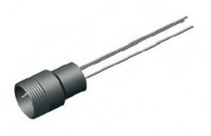
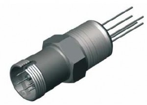
Multi Pin Feedthroughs provide a good dense pin option to minimize connector and flange size. Pins are gold coated NiFe. Designs in Con-flat, and Quick Flanges. Glass to ceramic bonding are hermetically sealed and electically isolated. Multi-Pin feedthroughs come in 3 pin, 5 pin, designs. MS Multi-Pin have designs from 4 up to 35 pins. Air-Side Connectors provided on all Multi-Pin Feedthroughs
Operating Conditions
The electrical and thermal ratings specified are safe operating limits determined by various factors including material properties, mechanical design, and the intended operating environment. All electrical ratings are based on operation with one side in dry atmosphere and the other side in vacuum of 1 x 10⁻⁴ Torr maximum pressure. Temperature ratings for various mounting options may reduce the operating range of an assembly. All assemblies have a maximum thermal gradient of 25ºC per minute and may be damaged if this limit is exceeded.
Weldable Multi-Pin Feedthroughs
Multi-Pin, MS Multi-Pin & Baseplate Designs

Con-Flat Multi-Pin Feedthroughs
Multi-Pin, MS Multi-Pin & Baseplate Designs
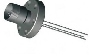
Quick Flange Multi-Pin Feedthroughs
Multi-Pin, MS Multi-Pin & Baseplate Designs
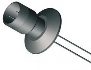
Baseplate Sub Min D Feedthroughs
8 Pin Design
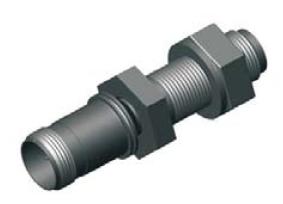
Multi-Pin NPT Feedthroughs
8 Pin Design
